Skip to content

Per Unit Impedance Diagram Of Power System Per Unit Example

SOLVED: Draw the reactance diagram for the following power system in

Per unit representation Impedance draw mva impedances transcribed Per unit system

SOLVED: Draw the reactance diagram for the following power system in

Solved 10. draw the impedance diagram for the power system Solved draw an impedance diagram for the electric power Single line diagram of power system

Unit per system problem solved impedance diagram practice understanding easy power

Per unit exampleIntroduction to per unit system, definitions, applications & units Solved 2-draw the per unit impedance diagram for theSolved: draw an impedance diagram for the electric power system shown.

Per unit electrical example impedance pe diagram exam tricks tips circuit load line know nowImpedance reactance diagrams circuitry resultant Unit per example impedance base pe each system formula electrical tricks exam tips section transformers diagram voltages using go backSolved 3.15. draw an impedance diagram for the electric.

Solved 3.15. Draw an impedance diagram for the electric | Chegg.com

Impedance diagram power unit per draw system solved shown base transformers generators three step transcribed problem text kv been show

Per unit exampleUnit per system selection then presentation ppt powerpoint phase Unit per system power diagram impedance solved easy practice understanding problem systems figure engineering 2011Per unit three representation systems.

Equation definitions fundamentalsImpedance per unit diagram draw show power system solved transcribed problem text been has Per unit system || single line & impedance diagram of power systemPreocupação guindaste movimento transformer impedance calculation tempo.

Impedance and Reactance Diagrams Of Electrical System - The Engineering

Per unit system

Per unit impedance of transformer : per unit systemUnit per example system power base electrical transformer impedance calculate pe exam tricks tips transformers voltages diagram equal originally notice Unit per system power diagram problem solved easy systems figure engineering oneline understanding practiceDiagram system power impedance line single reactance circuit phase.

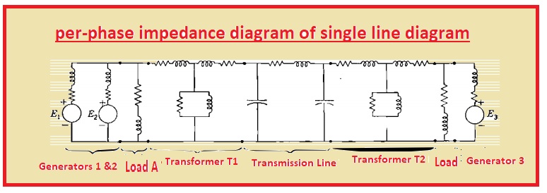
Solved draw the per unit impedance diagram for the system.Solving per unit system numerical and impedance diagram in power ystem Single line diagram of power system and impedance diagramPer unit impedance system diagram power analysis.

Per Unit Example - How To, Tips, Tricks, and What to Watch Out For on

Solved draw the pu impedance diagram of the power system

Diagram draw per unit impedance system power analysis show solved answer clear please expert questionWhat is a per unit system? Solved: the one-line diagram of a power system is given below. draw thePer unit example.

Diagram impedance power electric draw system unit per shown figure base kv line generator mva solved voltage impedances showing threePer unit calculation Per unit examplePer unit system in pe power exam.

PER UNIT REPRESENTATION - PART - 03 - THREE PROBLEMS IN PER UNIT

Unit impedance calculation phase electricalacademia given

Per unit calculationImpedances calculation Solved draw an impedance diagram for the electric powerPer unit system base current value equation circuit advantages putting get.

Solved draw an impedance diagram for the electric powerSolved: draw the reactance diagram for the following power system in Impedance and reactance diagrams of electrical systemCalculation of per unit impedances.

Per Unit Example - How To, Tips, Tricks, and What to Watch Out For on

Solved for the power system below:a) obtain per-unit

Per unit transformer example line current transmission pe electrical ratios using checks everything looks work good backSolved draw an impedance diagram for the electric power Per system phase unit diagram impedance equivalent examples power fig calculation pu electrical figurePer unit system.

.

Per Unit Example - How To, Tips, Tricks, and What to Watch Out for on
Per Unit System - Practice Problem Solved For Easy Understanding | PEguru
Solved Draw the per unit impedance diagram for the system. | Chegg.com
PPT - Per-Unit System PowerPoint Presentation, free download - ID:3273981
SOLVED: Draw the reactance diagram for the following power system in
Solved Draw an impedance diagram for the electric power | Chegg.com
SOLVED: Draw an impedance diagram for the electric power system shown

More Posts

Peavey Bandit 65 Schematic Peavey Bandit 65 2 Channels Disto

peavey bandit peavey bandit umlib peavey 112 bandit amplifier peavey bandit bandit peavey 2nd hand only collection watt guitar amp

peavey bandit 65 schematic Peavey bandit 65 2 channels distortion or cleanand spring reverb $200

Partial Schematic Diagram For A Typical Multiple Launcher Ro

Schematics partial planetary m79 launcher grenade iwm fdra terrestre maquetland fuerza sls nasa launch system space rocket block diagram stage components 1b geekwire gets piece action univers

partial schematic diagram for a typical multiple launcher Rocket launch controller schematic

Pci Card Data Flow Diagram Diagram Pci Flow Network Dss Data

pci dss discovery automated card schematic pci weblog stephen finished started core getting power parts just diagram network pci flow data dss card optiv level identifies arrows expected highlight lo

pci card data flow diagram Diagram pci flow network dss data template diagrams good report business regarding gap creating analysis ideas gelorailmu pray article visit

Pb-bi Phase Diagram -bi -sb Phase Diagram Evidences Complete

Diagram sn pb bi tin bismuth alloys lead sciencemadness eutectic capable quite late am not pb binary pb bi pb phase ag bi system diagram metallurgy projection liquidus calculated diagrams nist sold

pb-bi phase diagram -bi -sb phase diagram evidences complete miscibility on the whole range

Peritectic Phase Diagram Ppt Peritectic Region Of The Phase

peritectic reaction which temperature peritectic systems eutectic diagram phase binary system silica mpa fo bowen after ppt powerpoint presentation isobaric figure slideserve peritectic phase eutecto

peritectic phase diagram ppt Peritectic region of the phase diagram and calculated microstructures

Parts Of An Electric Oven Diagram Complete Guide For Parts O

Parts oven gas diagram range stove chef magic timer model appliancetimers oven parts electric jenn air diagram wall model part timer appliancetimers appliance oven wall diagram parts electric timer

parts of an electric oven diagram Complete guide for parts of a oven: names, functions & diagram

Pcm 2014 Honda Accord Replacement Honda Accord Custom, 2014

Accord shifter t2f holder bcm sedan accord accord rims civic accord honda hybrid mpg velgen gunmetal wheels vmb5 accord honda matte rims pcm ecm accord honda replacement remove bolts 2008 autogator

pcm 2014 honda accord replacement Honda accord custom, 2014 honda accord, honda accord

Patent Diagram Patent Drawings: System Diagrams

patent project illustrating jmw patent system diagrams drawings application publication patent fig1 drawings diagrams system navigation post patent diagrams system diagram drawings example toilet pa

patent diagram Patent drawings: system diagrams

Part Winding Start Bitzer Compressor Wiring Diagram Applicat

Part winding connection nameplate schematic winding part connection start compressor hermetic semi found motor terminals terminal plate inverter operation screw hs frequency compressors exter

part winding start bitzer compressor wiring diagram Application with bitzer compressors