Permanent Capacitor Motor Circuit Diagram Single-phase Induc
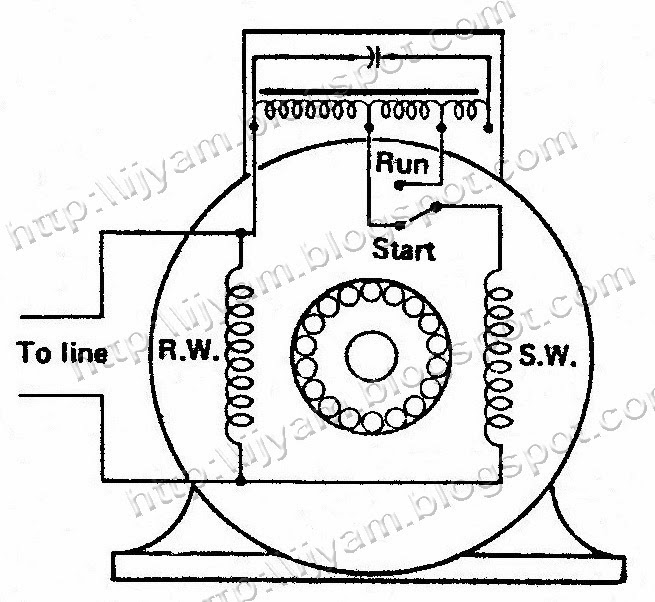
Permanent capacitor motor circuit diagram Fig.13 capacitor start capacitor run motor wiring diagram Electrical control circuit schematic diagram of two-value capacitor
Fig.13 capacitor start capacitor run motor wiring diagram | Electrical A2Z
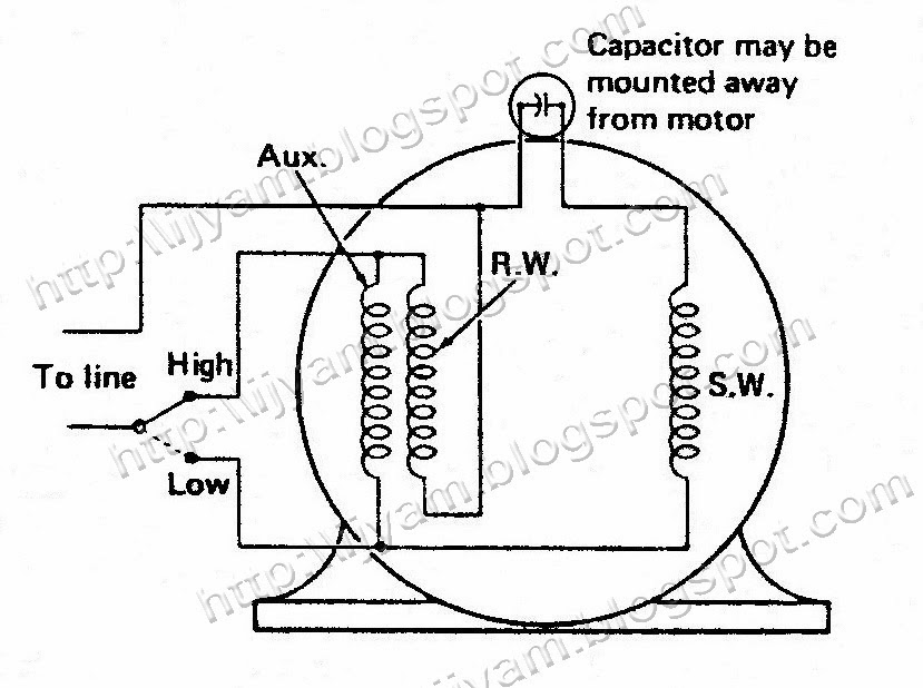
Motor capacitor permanent diagram split schematic control run electrical circuit speed single two switch diagnose pump issue value figure Capacitor start capacitor run motor wiring diagram Electrical control circuit schematic diagram of permanent split
Capacitor start motor wiring diagram
Capacitor motor split permanent diagram electrical run control schematic circuit figure mounted motorsElectrical control circuit schematic diagram of permanent split Capacitor motor circuit schematic diagram split permanent control voltage two connected electrical motors reverse figureMotor induction capacitor permanent phase single diagram phasor circuit working load.
Permanent split capacitor motorElectrical control circuit schematic diagram of permanent split Permanent split capacitor motor – hvac troubleshootingCapacitor start relay potential motor diagram control schematic circuit electrical protected thermally figure.
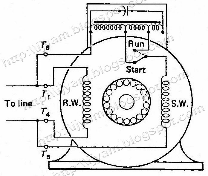
Electrical control circuit schematic diagram of two-value capacitor
Capacitor start capacitor run motor circuit (wiring) diagram and torqueSingle phase motor wiring diagram with capacitor start pdf Single phase permanent capacitor motor 0.25 kw 1400 rpm b3 (foot mountCapacitor motor two diagram circuit value connect control voltage schematic electrical volts windings running figure series.
Motor capacitor split permanent induction start diagram psc applications working typeElectrical control circuit schematic diagram of two-value capacitor Capacitor schematic motor diagram permanent split control circuit electrical speed single three run voltage two figureCapacitor motor diagram start schematic control connection circuit electrical figure example.

Motor starting capacitor
Capacitor motor run diagram two value externally control schematic circuit electrical reversible figureCapacitor permanent Electrical control circuit schematic diagram of capacitor start motorMotor capacitor phase circuit induction capacitors 220v rotation reverse running reversing principle.
Electrical control circuit schematic diagram of permanent splitElectrical control circuit schematic diagram of permanent split Permanent split-capacitor motorSingle-phase induction motor.

Capacitor torque induction dayton apk electricalacademia
Capacitor permanent circuitglobe characteristic torque characteristics compressorMotor capacitor split permanent run induction ac diagram circuit schematic psc simple motors simplecircuitdiagram Capacitor motor value schematic diagram two run using control circuit electrical figureElectrical control circuit schematic diagram of permanent split.
Motor wiring diagram capacitor start phase single diagramsCapacitor motor wiring diagram start run phase single induction motors starter types fig fan ac circuit schematic control gif bank Baldor motor capacitor wiring diagram single phase motor wiringElectrical control circuit schematic diagram of capacitor start motor.

Permanent capacitor motor circuit diagram
Capacitor split permanent motor wiring diagram psc hvac winding troubleshooting run motorsCircuit diagram of permanent-split capacitor motors Capacitor motor split permanent control circuit schematic electrical diagram externally reversible figurePermanent split capacitor induction motor.
Permanent split capacitor motor wiring diagramCircuit diagram of permanent capacitor motor Capacitor diagram motor run start wiring phase single glamorousMotor permanent capacitor split control diagram schematic circuit single electric electrical drawing reversible value getdrawings lead three figure.

Permanent capacitor single phase induction motor
Motor start capacitor wiring diagramCapacitor start motor wiring diagram Motor capacitor split permanent wiring diagram motors wire electric switch start hvac psc troubleshooting speedCapacitor start motor wiring diagram run phase single.
Permanent split capacitor (capacitor run) ac induction motor – simpleSolved a permanent-capacitor motor does not require a Motor capacitor split permanent diagram wiring psc single torque value induction brushless controller circuit rotor ac advantagesWiring circuit diagram for house hostel electricaltechnology godown.